
I found this after days of digging so i thought i would post it here for any one who wants it. I am also open to ideas on how to change this mod or make it better or if it is even right in the first place...... So here you guys go
NPC-RC Modification for 6900xxx Type Boards
OK guys and gals a little studying needs to be done here but if you havent noticed the 6900xxx board found in say the galaxy 94hp and the 069610Z board of the Galaxy 949/959 are basically the same even part numbers are the same,, so I will do only one to save time……
On SSB radios it is necessary especially if the user uses SSB to run an alignment on the radio especially checking driver and final bias and use a pen or some whiteout to mark the VR’s cause once TP8 clip is gone you will only have the mark to go by…..
Parts needed 1- 1n4001 diode
2- 100ohm resistor
3- 6 inch piece of 18guage stranded wire
Step 1- Take the diode and resistor and solder the banded end of the diode to the resistor…Then fold the other end of the resistor down to form kinda like a hair pin….(see attachment 1)
Step 2- C233 needs to be removed from the board and saved for use in another step (see attachment 2)
Step 3- Now take diode resistor combo and place where C233 was with diode lead in the hole facing the front of the radio and the resistor lead in the hole facing the rear of the radio.. Now solder diode resistor combo in place then take the capacitor you took out of C233 and solder to the diode resistor combo on the solder side of the board .. Make sure the cap if as flat as possible so it doesn’t interfere with the top case lid..
Step 3- Look near the final you will see a Bias board on SSB radios and a set of jumpers on AM/FM only radios, this is where TP7,8,and 9 are,, on this board TP8 needs to be removed,, on SSB radios there is a clip for TP8, remove the clip then replace the bias board…. ON AM/FM only radios you need to remove the jumpers from TP8 and lift out of the hole and then solder together so now the jumper goes from TP7 to TP9 bypassing TP8.…(see attachment 3)
Step 4- Take your piece of 18 gauge wire and strip 1/8” off each end and tin with solder,, now where you removed the clip or jumpers from TP8 solder one end of the wire to this point on the solder side of the board,, now solder the other end to the 12v rail of the emitter of Q54 (see attachment 4)
Step 5- R276 needs to be disabled this is the AMC for this radio and by disabling this resistor on SSB radios the SSB should not be affected,,, now you need to find Q57 and 39, if they are there and unmolested leave them alone and if they are missing replace them,, these are components of the AMC also but will affect SSB….(see attachment 5)
Step 6- The power needs to be retuned now.. The high power needs to be set first.. Put variable knob on the high setting now inside the radio look for VR14 set this for 7 watts on low power radios and for high power radios set for 25 watts.
Step 7- Put the power variable to the lowest setting,,, now adjust VR18 for 2 watts for low power radios and 5 watts if you desire for high power radios,, go back and check high power settings to make sure they are correct, if not, tune accordingly…. I would highly recommend the use of non conductive tuning sticks for steps 6 and 7.…
This is for educational purposes only,, I am not responsible if you burn your radio or mess it up in any way……
DX959 NPC/RC mod
-
dime196604

- Wordwide & Qualified

- Posts: 798
- Joined: October 26th, 2009, 2:20 pm
DX959 NPC/RC mod
It ain't broke till you smell the smoke
-
Night Crawler

- Wordwide & Qualified
- Posts: 3,836
- Joined: May 15th, 2007, 9:03 am
If your thinking about doing that modification I wouldn't if I were you.
-
dime196604
- Wordwide & Qualified
- Posts: 798
- Joined: October 26th, 2009, 2:20 pm
How come? Will it fry my radio faster? Or does it just make u sound like crap? I'm not doubting your judgment at all, just wanna know why it would be a bad ides to do it.Night Crawler wrote:If your thinking about doing that modification I wouldn't if I were you.
It ain't broke till you smell the smoke
-
355kylake
- 6 PILL USER

- Posts: 82
- Joined: July 21st, 2011, 4:06 pm
that is a complicated mod i would think about it before i started it
-
DB_Cooper

- 4 PILL USER

- Posts: 32
- Joined: June 5th, 2010, 3:39 pm
I just did the mod to a 949. I think it works great. Thanks for the info.dime196604 wrote:How come? Will it fry my radio faster? Or does it just make u sound like crap? I'm not doubting your judgment at all, just wanna know why it would be a bad ides to do it.Night Crawler wrote:If your thinking about doing that modification I wouldn't if I were you.
-
Night Crawler
- Wordwide & Qualified
- Posts: 3,836
- Joined: May 15th, 2007, 9:03 am
I wonder for how long?DB_Cooper wrote:I just did the mod to a 949. I think it works great.
-
DB_Cooper
- 4 PILL USER
- Posts: 32
- Joined: June 5th, 2010, 3:39 pm
I don't talk much so it may last quite a long time......lolNight Crawler wrote:I wonder for how long?DB_Cooper wrote:I just did the mod to a 949. I think it works great.
-
DB_Cooper
- 4 PILL USER
- Posts: 32
- Joined: June 5th, 2010, 3:39 pm
However, it would be nice if someone has issues with this mod, that they could share their specific concerns. If someone could site specific parts that failed or a condition that arose. :r&r:Night Crawler wrote:I wonder for how long?DB_Cooper wrote:I just did the mod to a 949. I think it works great.
-
Night Crawler
- Wordwide & Qualified
- Posts: 3,836
- Joined: May 15th, 2007, 9:03 am
Follow the steps in the modification while looking at the schematic for the 959 and you'll see why it's detrimental to the radios longevity.
If those parts needed to be added, parts removed and wires rerouted the design engineer would have already incorperated that into the circuit.
If those parts needed to be added, parts removed and wires rerouted the design engineer would have already incorperated that into the circuit.
-
hilltop 439

- Skipshooter

- Posts: 452
- Joined: November 7th, 2010, 1:07 pm
And so goes for all modifications just some are worse than othersNight Crawler wrote:Follow the steps in the modification while looking at the schematic for the 959 and you'll see why it's detrimental to the radios longevity.
If those parts needed to be added, parts removed and wires rerouted the design engineer would have already incorperated that into the circuit.
... THE ONLY WAY TO DISCOVER THE LIMITS OF THE POSSIBLE IS TO GO BEYOND THEM INTO THE IMPOSSIBLE ...
-
DB_Cooper
- 4 PILL USER
- Posts: 32
- Joined: June 5th, 2010, 3:39 pm
I take it that you are not in favor of the SWP modification then?hilltop 439 wrote:And so goes for all modifications just some are worse than othersNight Crawler wrote:Follow the steps in the modification while looking at the schematic for the 959 and you'll see why it's detrimental to the radios longevity.
If those parts needed to be added, parts removed and wires rerouted the design engineer would have already incorperated that into the circuit.
-
Night Crawler
- Wordwide & Qualified
- Posts: 3,836
- Joined: May 15th, 2007, 9:03 am
If your happy with it that's all that counts.
-
hilltop 439
- Skipshooter
- Posts: 452
- Joined: November 7th, 2010, 1:07 pm
Really the only mods that i am in favor of is frequency exspansion, changing the color of the LEDs and upgrading the existing components of the radio. Bigger more durable caps,resitor,diodes and such. As Night Crawler stated if these different swing mods and power inhancements really worked then the engineers would have incorporated them into there radio. I think a lot of these mods come from bored CB Frankinstiens that like to tinker with there radios and like it when there watt meters needle is bouncing from one side of the room to the other. This is all fine and good if that what you like to do but when these mods find there way into CB shops and web sites there becomes a lot more splatterboxes on the airwaves.
... THE ONLY WAY TO DISCOVER THE LIMITS OF THE POSSIBLE IS TO GO BEYOND THEM INTO THE IMPOSSIBLE ...
-
dime196604
- Wordwide & Qualified
- Posts: 798
- Joined: October 26th, 2009, 2:20 pm
Whats the SWP mod??DB_Cooper wrote:
I take it that you are not in favor of the SWP modification then?
It ain't broke till you smell the smoke
-
DB_Cooper
- 4 PILL USER
- Posts: 32
- Joined: June 5th, 2010, 3:39 pm
I hear what you are saying. I have to admit that I was surprised how well my radio sounded after I tried this mod. But like one poster mentioned, how long will it last. I don't know but so far it does very well. Actually this radio has some upgraded caps I put in too so that may be a factor. Who knows.......just playing around. You never know until you try.hilltop 439 wrote:Really the only mods that i am in favor of is frequency exspansion, changing the color of the LEDs and upgrading the existing components of the radio. Bigger more durable caps,resitor,diodes and such. As Night Crawler stated if these different swing mods and power inhancements really worked then the engineers would have incorporated them into there radio. I think a lot of these mods come from bored CB Frankinstiens that like to tinker with there radios and like it when there watt meters needle is bouncing from one side of the room to the other. This is all fine and good if that what you like to do but when these mods find there way into CB shops and web sites there becomes a lot more splatterboxes on the airwaves.
-
hilltop 439
- Skipshooter
- Posts: 452
- Joined: November 7th, 2010, 1:07 pm
And you are right DB_Cooper never know until you try. I guess thats the only way to learn hands on and trial and error. I am certainly know stranger to tampering with the inside of a radio and have seen and made my share of smoke clouds when it went wrong . I have learned to leave my new radios alone and use the ginypig radios for the solder iron.
... THE ONLY WAY TO DISCOVER THE LIMITS OF THE POSSIBLE IS TO GO BEYOND THEM INTO THE IMPOSSIBLE ...
-
dime196604
- Wordwide & Qualified
- Posts: 798
- Joined: October 26th, 2009, 2:20 pm
So how come this mod is hard on the radio? Why will it shorten the life of my final?
It ain't broke till you smell the smoke
-
DB_Cooper
- 4 PILL USER
- Posts: 32
- Joined: June 5th, 2010, 3:39 pm
As far as I know, it doesn't. I just did another radio today and it sounds great.dime196604 wrote:So how come this mod is hard on the radio? Why will it shorten the life of my final?
-
577-Jersey

- 4 PILL USER
- Posts: 23
- Joined: September 11th, 2013, 5:24 am
The mod only takes 15 min to do on either board 6900 or 3600 and works super,,i put it on a spst so the op can switch it in and out ,,if you dont like the results its very easy to return to stock,,FET rigs will run a tad hotter in the finals but as long as the bias voltage is 3.75v driver and 3.50v on gate of final you will be fine,,FET's are cheap enough if you pop one,,I have not seen one pop yet and have done hundreds of these to date355kylake wrote:that is a complicated mod i would think about it before i started it
577-Jersey
Friday, 13 September 2013, 20:54 PM
NPC/RC for the Galaxy 949/959 and others with 6900xxx board...
The way I do it is in the same locations BDW did but I use the solder side,,its easier.
1.remove bias board and pull center clip out(tp8) or bend tabs so they dont touch the bias board anymore.
2.clip or remove r-276
3.make sure q57,and q39 are still intact or ssb will garble,,also make sure r264 is not modded with a diode series.
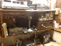
4.on trace side solder the 100ohm resistor in a series with the 1n4001-7 diode(band facing to right at final like in picture)from the traces shown...I use a little hot glue under the combo to hold it fast..you can heat shrink also..
5.now solder in the jumper wire(14 or 16 awg is fine) from 13volt trace to where tp 8 was(make sure to use top trace at tp8).AKA RWOB
6.turn all power pots down to zero,,then key and set power for 5 watts high and 2 watts low.
NOTE**
I would check your bias before you do the mod and make sure its good,,I never see the bias change after doing the mod.
If it has FETS and they are running a little hot you can lower the bias a little for less heat.I just set it off the gate for voltage,,3.75vdc for driver and 3.50vdc for final,,check it first and see what it is before mod.In order to check it after the RWOB on the final,,you have to remove the wire and put your AMP meter in series with the wire and tp 8,,but only for the final.
Hope that helps,,any ques.just ask.
Tom
BTW-I did not figure out how to post pics yet,,it would not let me post the board locations for some reason,,PM me with your email and I will get them out to you!
-
Tgriff89

- NEW DUCK

- Posts: 2
- Joined: October 11th, 2020, 3:15 am
I realize this is a very old thread but I am looking to return my 2517 back to stock. It has had this mod done to it and therefore T8 post has been removed. My question is what is the forked post called so that I can order a replacement connector at T8? I've looked through all the paperwork that I have containing any BOM info and I cannot find the part #.
