MOSFETs vs. Pills
-
Shaft
MOSFETs vs. Pills
Can any one tell me why amps use the pill type transistors instead of a bank of MOSEFT type? It seems that an amplifier made with MOSFETs would run cooler and could be smaller in size.

-
HI-TECH
because the mosfet's in our neck of the woods (11m RF) is just now starting... there a little more expensive to produce then you would a homemade 2 or 4trasistor amp.... but they deff do run cool and dose not use crap for power. i had a 300W mosfet amp from a former sponsor think only drew maybe 5 amps @ peak on the high side...low side i could run both the radio and my amp off my other 5amp power supply and be doing 130 watts it was awesome 
-
treetall

- Wordwide & Qualified

- Posts: 582
- Joined: March 23rd, 2008, 8:26 am
- Handle: treetall
- Real Name: Carrington
- Radio: Galaxy
- Contact:
man i havent even thought about an mosphet amp. but i think ill stick with my pills cause i have a feeling a pill is cheaper and more common to replace than a mosphet but it would be interesting to see one of those boxes like you were talking about Hi tech
801 working this baby driver in the carolinas getting out the way.
-
Foxhunter

- Donor

- Posts: 2,651
- Joined: April 3rd, 2008, 11:24 am
- Radio: Fisher-Price
- Contact:
There are a number of commercial RF amplifier manufacturers already using FET or MOSFET type transistors in their RF amplifier designs. How long until it becomes more widespread in the 11M world here is still a good question. Once again (and sadl)y, foreign makers seem to be leading the way.
While researching and following up on many of the RF amplifier builders and manufacturers in the "Amp Builder History?" thread, to my surprise I found a number of the Amateur Radio manufacturers were producing FET amplifiers. http://www.cbradiotalk.com/vi ... 858#215858
This German manufacturer Alpin below for instance produces a 1000W all MOSFET linear amplifier.
Also RM Italy, which has many amplifiers available here in the US (they are HUGE overseas) actually have many in their product line that are MOSFET powered. They provide both HF & VHF amplfiers which include Citizens Band.
http://www.rmitaly.com/home.asp
There are many more also doing the same. I wonder if it will ever get to the "MOSFET Comp Box" level with "custom-built" CB amps.
Additionally, from reading it seems there possibly is an advantage to be gained in the use of a IR HEXFET transistor over the MOSFET type. Regardless, what Shaft was saying is an absolute as far as the advantage the MOSFET has over the bi-polar Toshiba type transistors we all now seem to be enjoying, using, and sometimes burning up. For any CBRT Forum viewers or visitors, the following excerpt maybe best sum up why.
While researching and following up on many of the RF amplifier builders and manufacturers in the "Amp Builder History?" thread, to my surprise I found a number of the Amateur Radio manufacturers were producing FET amplifiers. http://www.cbradiotalk.com/vi ... 858#215858
This German manufacturer Alpin below for instance produces a 1000W all MOSFET linear amplifier.
http://www.reimesch.de/expert_en.html**ALPIN --by Reimesch Kommunikationssystemme aka SPE-- (ALPIN 100 / ALPIN 100 MKII / ALPIN 200 / EXPERT 1K-FA *three versions)
Also RM Italy, which has many amplifiers available here in the US (they are HUGE overseas) actually have many in their product line that are MOSFET powered. They provide both HF & VHF amplfiers which include Citizens Band.
http://cbradiomagazine.com/Ma ... lifier.htmRM Italy (KL 35 / KL 40 / KL 60 / KL 200 / KL 200 P / KL 203 / KL 300 / KL 300 P / KL 400 / KL 500 / KL 300 24 / KL 500 24 / KLV 350 / KLV 400 / KLV 550 / KLV 1000 / KLV 1000 P / KL 144 / KL 155 / KL 145 / KL 145H / VLA 100 / VLA 100 1 / VLA 200 / VLA 200 1 / VLA 200 2 / V ULA 50 / KLV 250 / K 27M / 27 586 / KL 43 / KL 243 / KLV 250 VIP / KLV 200 VIP / KLV 350 VIP / KLV 400 VIP / KLV 1000 VIP / KLV 1000 P VIP / VLA 200V / VLA 100V / HLA 150 Plus / HLA 150 V Plus / HLA 300 Plus / HLA 300 V Plus / VLA 150 / BLA 300 / KL 501 / KL 501 VIP / KL 800 / V-ULA 50)
http://www.rmitaly.com/home.asp
There are many more also doing the same. I wonder if it will ever get to the "MOSFET Comp Box" level with "custom-built" CB amps.
Additionally, from reading it seems there possibly is an advantage to be gained in the use of a IR HEXFET transistor over the MOSFET type. Regardless, what Shaft was saying is an absolute as far as the advantage the MOSFET has over the bi-polar Toshiba type transistors we all now seem to be enjoying, using, and sometimes burning up. For any CBRT Forum viewers or visitors, the following excerpt maybe best sum up why.
Secondary Breakdown
An attraction in choosing the MOSFET transistor in preference to the bipolar transistor is the absence of second breakdown. An explanation of this, extracted from the IR handbook, is given in the following paragraph:
One of the outstanding features of IR's power MOSFET is that they do not display the second breakdown phenomenon which is frequently the Achilles heel of bipolar transistors. A simple physical explanation accounts for this superiority. If localized potentially destructive heating occurs within a MOSFET transistor, the carrier mobility in that area decreases. As a result the MOSFET has a positive temperature coefficient and acts in a selfprotective manner by forcing currents to be uniformly distributed through the silicon die. In contrast and particularly under conditions of high collector-emitter voltage, a bipolar transistor displays "current crowding" in the base region. This causes hot spots. Because of the bipolar's negative temperature coefficient, these hot spots tend to further "hog" the current and cause instantaneous catastrophic destruction of the die.
-
zman350

- Donor
- Posts: 385
- Joined: October 30th, 2008, 8:46 pm
- Contact:
-
Foxhunter
- Donor
- Posts: 2,651
- Joined: April 3rd, 2008, 11:24 am
- Radio: Fisher-Price
- Contact:
-
North Texas Mudduck
- Wordwide & Qualified
- Posts: 2,921
- Joined: September 30th, 2006, 8:22 pm
- Contact:

-
lonesome 500

- Donor
- Posts: 1,779
- Joined: June 8th, 2007, 3:40 pm
-
drdx

- Donor
- Posts: 5,944
- Joined: April 25th, 2007, 12:32 pm
- Handle: dollar-98
- Real Name: David
- Antenna: Many
- Radio: Many-
- Contact:
I believe Tokyo hi-power builds kw plus amps using them, and many newer ham rigs use them as well. I'd guess it is just a matter of time. It will be funny when the 2879 is seen as "old school" like we see tube stuff today. Will that ever happen? Who knows, but stuff changes all the time. Years ago, 100 watts mobile was a big deal, look at it now. That's MAYBE the deadkey on a guy's driver these days. I got into a conversation with 2 other mobiles today. One guy had a 500 watt carrier, 1500 swing, the other a 400/1000 setup, and neither are considered real players. What will it be in 20 years?
-drdx
-drdx
Yes it's me, Dollar-98, drdx, the original all maul, shot cawla on workin this no-fade technology.
-drdx
-drdx
-
Gummybear

- Skipshooter

- Posts: 349
- Joined: January 17th, 2009, 8:43 pm
- Real Name: Samual
- Radio: 2-way baby monitor
- Contact:
-
lonesome 500
- Donor
- Posts: 1,779
- Joined: June 8th, 2007, 3:40 pm
-
Gummybear
- Skipshooter
- Posts: 349
- Joined: January 17th, 2009, 8:43 pm
- Real Name: Samual
- Radio: 2-way baby monitor
- Contact:
HI-TECH wrote:.... but they deff do run cool and dose not use crap for power. i had a 300W mosfet amp from a former sponsor think only drew maybe 5 amps @ peak on the high side...low side i could run both the radio and my amp off my other 5amp power supply and be doing 130 watts it was awesome
Then what is he talking about??? sorry Hi-tech for throwing you under the bus... :D I just need the facts...
-
lonesome 500
- Donor
- Posts: 1,779
- Joined: June 8th, 2007, 3:40 pm
-
Gummybear
- Skipshooter
- Posts: 349
- Joined: January 17th, 2009, 8:43 pm
- Real Name: Samual
- Radio: 2-way baby monitor
- Contact:
-
plutonium233
- 6 PILL USER

- Posts: 50
- Joined: December 20th, 2008, 12:04 am
Overdriving a BJT to gross levels will, in fact, cause "secondary breakdown" where Vce (collector-emitter voltage) goes to near zero and the Ic (collector current) runs away. This usually leads to what EE's call burning, or more commonly called blowing or popping the transistor, and it is due to exceeding the design limits of the transistor such as TJ(max) and Ic(Max). As Vbe increases from zero the transistor goes from cutoff, to the active mode of operation and then on to saturation(bad) then the secondary breakdown region(really bad). This stems from two factors in how a BJT operates which are time consuming to explain, but it has to do with the biasing of the base region of the transisitor and some complicated phyisical phenomena (such as tunneling) involving the carriers(holes/electrons).
This is not such a problem with MOSFETs since the the n-channel or p-channel can only reach a certain maximum width for any given gate voltage. The transistor operates in cutoff, triode, and saturation where saturation is the desired mode of operation for amplifiers. The drain current does have a design limit that can't be exceeded so you can still burn them; however, there is no gate current to speak of (on the order of pA and fA) whereas the gate current in an overdriven BJT just makes it dissipate more heat and lets thermal runaway occur faster.
The only way the MOSFETS will be better is if Pd (Power dissipated) is lower per watt out of the amp (PL). This just means it is more efficient. This could come from the fact there is no gate current to deal with. The other thing is that it may operate more efficiently with a given biasing (Class C, AB) than a BJT in the same situation. I am not sure since I haven't studied the use of MOSFETs as output stages in Class C settings yet. I'll have to dig out my book and see what I can find out anything else.
-
Foxhunter
- Donor
- Posts: 2,651
- Joined: April 3rd, 2008, 11:24 am
- Radio: Fisher-Price
- Contact:
-
plutonium233
- 6 PILL USER
- Posts: 50
- Joined: December 20th, 2008, 12:04 am
I just made a couple minor corrections/additions. I also want to clarify for those who don't know:plutonium233 wrote:Overdriving a BJT to gross levels will, in fact, cause "secondary breakdown" where Vce (collector-emitter voltage) goes to near zero and the Ic (collector current) runs away. This usually leads to what EE's call burning, or more commonly called blowing or popping the transistor, and it is due to exceeding the design limits of the transistor such as TJ(max) and Ic(Max). As Vbe increases from zero the transistor goes from cutoff, to the active mode of operation and then on to saturation(bad) then the secondary breakdown region(really bad). This stems from two factors in how a BJT operates which are time consuming to explain, but it has to do with the biasing of the base region of the transisitor and some complicated phyisical phenomena (such as tunneling) involving the carriers(holes/electrons).
This is not such a problem with MOSFETs since the the n-channel or p-channel can only reach a certain maximum width for any given gate voltage. The transistor operates in cutoff, triode, and saturation where saturation is the desired mode of operation for amplifiers. The drain current does have a design limit that can't be exceeded so you can still burn them; however, there is no gate current to speak of (on the order of pA and fA) whereas the gate current in an overdriven BJT (Pill) just makes it dissipate more heat and lets thermal runaway occur faster.
The only way the MOSFETS will be better is if Pd (Power dissipated) is lower per watt out of the amp (PL). This just means it is more efficient. This could come from the fact there is no gate current to deal with. The other thing is that it may operate more efficiently with a given biasing (Class C, AB) than a BJT in the same situation. I am not sure since I haven't studied the use of MOSFETs as output stages in Class C settings yet. I'll have to dig out my book and see what I can find out anything else.
BJT: Base, Emitter, Collector which is analagous to MOSFET: Gate, Source, Drain
-
plutonium233
- 6 PILL USER
- Posts: 50
- Joined: December 20th, 2008, 12:04 am
-
madsage
- Wordwide & Qualified
- Posts: 511
- Joined: December 17th, 2006, 10:12 am
- Real Name: RiFFRaFF
- Radio: Magnum S45, Cobra2K
- Contact:
Re: MOSFETs vs. Pills
Also keep in mind, OHMs Law only applies to DC power. Not AC RF
We have to use RMS values which is AC power in DC equivilence.
AC power in watts at RMS value is equal to DC power.
1kw RF PEP is only equiv to about 400watts DC. depending on modulation and other variables.
You typicaly use a 1000hz tone audio signal for reference point.
73 from
933 riffraff
in the stickers
-
216
- 6 PILL USER
- Posts: 53
- Joined: June 22nd, 2007, 9:13 am
Re:
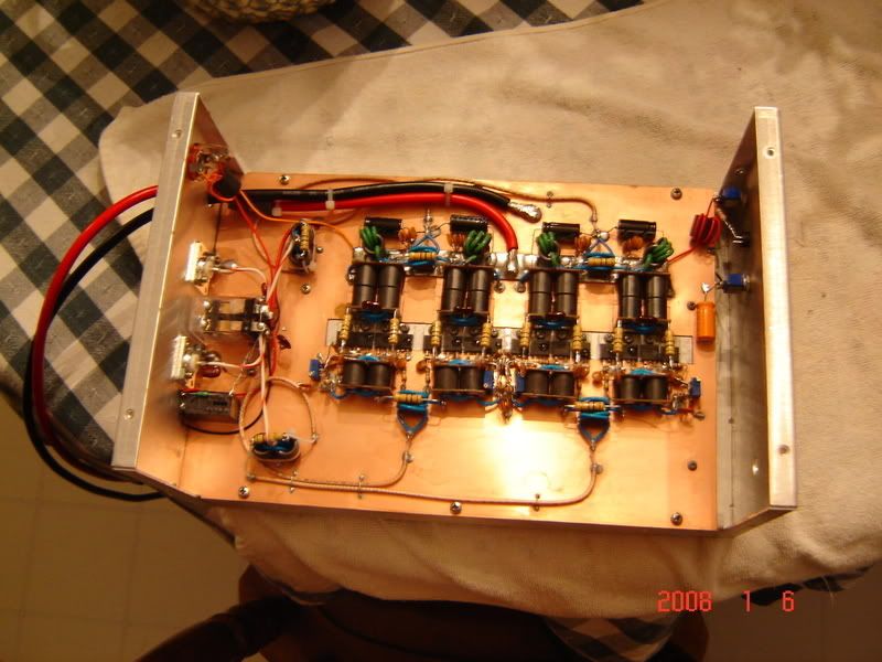
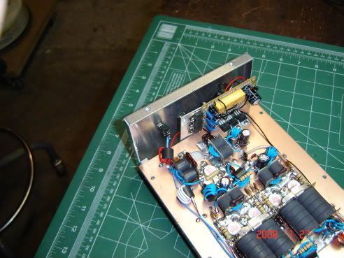
zman350 wrote:here is something to look at.
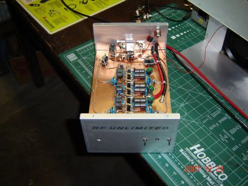
Thats one of my experiments that worked out very well,16 IRF520's @60 cents apiece.
3.75 watts in gives 100 watts out,swings 400pep read on a Bird43.Ill sell it eventually and build another using a 4port splitter and combiner instead of 2.
Heres a front pic
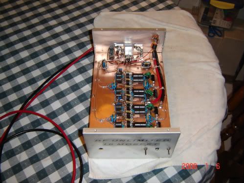
Another precision built amplifier from myself,regulated biased AB with thermal tracking at the driver and finals. 1x4,2290 driving 2879's.All holes drilled and tapped,transistors and heatsink lapped to make everything perfectly flat.No sheetmetal screws in my shop.
-
127
Re: MOSFETs vs. Pills
It has been posted many times that Mosfets blow a lot easier than standard pills. Overdrive a mosfet and they're done.
Call me old fashioned but if it can't take a licking and keep on ticking, it's not for me.
Call me old fashioned but if it can't take a licking and keep on ticking, it's not for me.
-
lonesome 500
- Donor
- Posts: 1,779
- Joined: June 8th, 2007, 3:40 pm
Re: MOSFETs vs. Pills
huh?madsage wrote:Also keep in mind, OHMs Law only applies to DC power. Not AC RF
We have to use RMS values which is AC power in DC equivilence.
AC power in watts at RMS value is equal to DC power.
1kw RF PEP is only equiv to about 400watts DC. depending on modulation and other variables.
You typicaly use a 1000hz tone audio signal for reference point.
73 from
933 riffraff
in the stickers
ohms law applies to ac or dc......in current - voltage and output....or resistance
the reference was....you don't get ''more'' out than you put in/consume
and rms output....is the only thing i look at
<center>
<a><img></a>
</center>
<a><img></a>
</center>
-
216
- 6 PILL USER
- Posts: 53
- Joined: June 22nd, 2007, 9:13 am
Re: MOSFETs vs. Pills
RMS doesnt apply here unless you have an rms wattmeter? lol.every wattmeter i know of including Bird reads average or pep.
-
127
Re: MOSFETs vs. Pills
lonesome 500 wrote:huh?madsage wrote:Also keep in mind, OHMs Law only applies to DC power. Not AC RF
We have to use RMS values which is AC power in DC equivilence.
AC power in watts at RMS value is equal to DC power.
1kw RF PEP is only equiv to about 400watts DC. depending on modulation and other variables.
You typicaly use a 1000hz tone audio signal for reference point.
73 from
933 riffraff
in the stickers
ohms law applies to ac or dc......in current - voltage and output....or resistance
the reference was....you don't get ''more'' out than you put in/consume
and rms output....is the only thing i look at
Less power draw but more output? That guy named Ohm sure was wrong.
